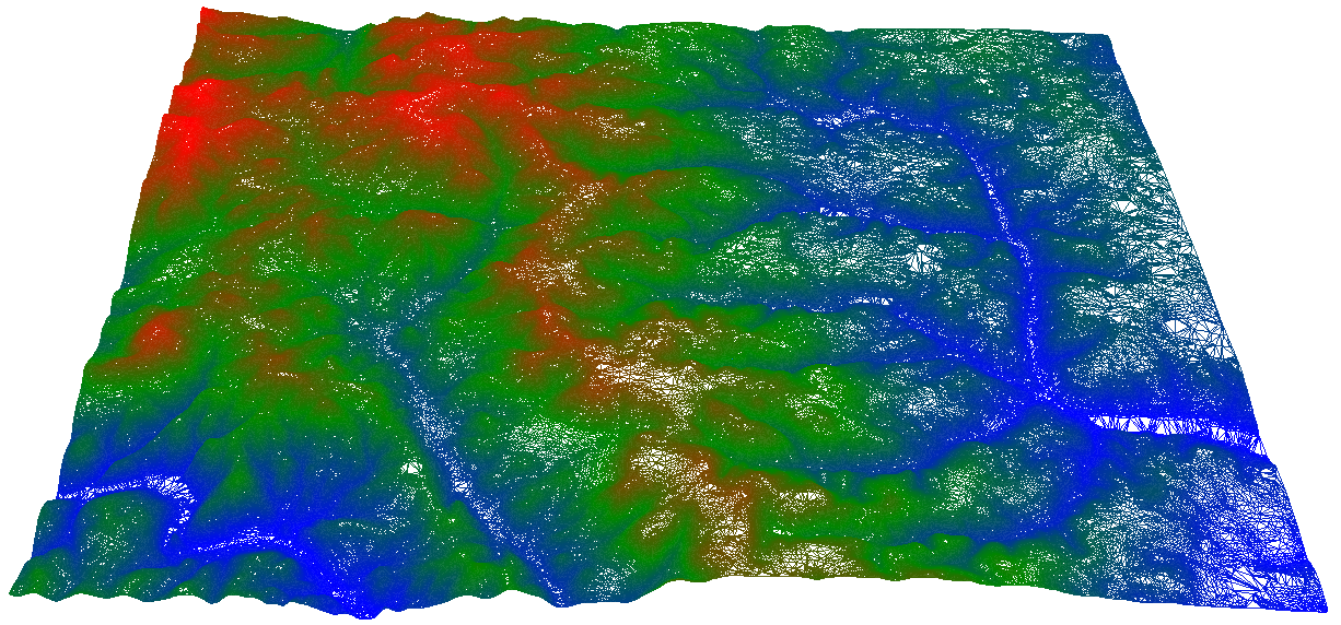
3D view of digital elevation model(DEM) with vertical exaggeration (x10)
When working in an area where there is no fit-for-purpose topographic data collected for use on a project in the conterminous United States, Alaska, Hawaii, U.S. island territories, Mexico and Canada, contours generated from a Digital Elevation Model (DEM) from the National Elevation Dataset (NED) may be a suitable substitute to get an idea of the lay of the land. A good example of this application is when there is a requirement to calculate and understand variables based on neighborhood derived land parameters such as aspect and slope.
For uses that require a higher level of accuracy like building pads, roads and parking lots, it is always better to collect original data fit for purpose for a particular project’s measurement tolerances.
For high level assessments to see how different parts of an area sit relative to each other, it is acceptable to use contours generated from a National Elevation Dataset DEM bearing in mind that the vertical accuracy of DEMs varies significantly across the U.S. because of differences in source quality, terrain relief, land cover, and other factors. 1
The steps to generate contours below from the National Elevation Dataset DEM (the DEM at the top of this article) are as follows:

We first download the DEM from the National Elevation Dataset website with USGS National Map Viewer. This particular DEM was downloaded at a resolution of 1/3 arc second. The downloaded file is processed in ArcGIS.
The elevation data is provided by the USGS in meters. It needs be converted to feet if we want to use the customary linear unit in the U.S. The meters to feet conversion is accomplished in ArcGIS with the Raster Calculator in Spatial Analyst. To remove the potential for creating jagged lines due to the pixel grid nature of the DEM before generating contours, the DEM must be smoothed. Focal Statistics in Spatial Analyst is the tool for the job.
To generate contours in the next step, we run the Contour function in the Surface Toolset of the Spatial analyst. The contours are generated by default in a 2D format with units in “decimal degrees” for Xs and Ys. The data needs to be projected to get a linear unit, in our case, the foot. This is analogues to projecting the 3D earth on a 2D surface based on various parameters.
The final step is to convert the 2D contours into 3D contours with the Feature to 3D tool in 3D Analyst. The contours can now be exported out of ArcGIS in a DWG format ready for use in CAD packages such as AutoCAD, Rhino, 3DS or any other program that can read .dwg files.